

Most people aim air movers at the wet drywall and think they’re drying the framing behind it. They’re not. Drywall comes off easily and costs maybe two dollars a sheet to replace. The framing behind it costs thousands if you let it stay wet long enough to rot or grow mold. Where you point those fans determines whether you’re just moving humid air around or actually pulling moisture out of studs, joists, and plates. Get the angle and spacing right, and framing dries in days. Get it wrong, and you’re sealing problems into the walls.
Strategic Air Mover Positioning for Effective Framing Dryout

Angle air movers at 45 degrees toward wet framing surfaces. That’s the fundamental placement principle for effective structural drying. This angle maximizes evaporation rate across wood grain and surface area, whether you’re drying studs, joists, or top plates. The 45 degree positioning follows IICRC S500 standard of care for water damage restoration, striking the balance between airflow velocity and coverage area that moves moisture off wood surfaces efficiently without over drying or creating excessive air turbulence that reduces effectiveness.
IICRC S500 provides baseline equipment requirements that remove guesswork from setup. Start with 1 air mover per affected room minimum, regardless of size. Add 1 additional unit per 50 to 70 square feet of wet floor and lower wall framing (up to approximately 2 feet high). Add 1 unit per 100 to 150 square feet of upper wall and ceiling framing. Add 1 unit for each wall inset or offset exceeding 18 inches. These calculations ensure adequate airflow reaches all affected framing members, not just the most visible damage. A 12 by 15 foot room with water affecting floor framing and two walls would require roughly 4 to 5 air movers based on these standards.
Position units to create consistent directional airflow along framing members. Move air across stud faces and into wall cavities when accessible, with all units moving air in the same rotational direction around the space. This directional strategy prevents opposing airflows that cancel velocity and create stagnant humid pockets where moisture lingers. Start with the wettest section and work around the room perimeter, establishing a circulation pattern like a gentle vortex flowing clockwise or counterclockwise depending on room layout and entry points.
Space air movers every 10 to 16 feet along affected framing runs, maintaining 12 to 18 inches distance from the surface. Closer placement concentrates drying power but risks localized over drying that can damage wood grain and connections. Greater spacing reduces equipment quantity but may leave gaps where airflow velocity drops below effective levels. The 12 to 18 inch standoff distance allows airflow to spread across the surface while maintaining enough velocity for moisture removal. Adjust this spacing tighter (toward 10 feet) for very wet conditions or Class 3 or 4 losses, and wider (toward 16 feet) for lighter water intrusion.
Dehumidifiers must operate alongside air movers. This is non negotiable. Fans facilitate evaporation, pulling moisture from framing materials into the air. Dehumidifiers extract that moisture from the air environment, preventing it from re absorbing into structural materials as temperature and humidity conditions fluctuate. Running air movers without dehumidifiers just moves wet air around the space. The moisture stays in the environment, settling back into framing, insulation, and finishes as soon as air movement stops or temperatures drop overnight.
Key CFM and Equipment Specifications:
Most structural drying applications require 1,200 to 3,000 CFM per unit for adequate air velocity across framing surfaces. Professional units draw 2.5 to 5 amps requiring circuit capacity planning to avoid overloading 15 amp household circuits. Axial fans provide high airflow for open framing and exposed surfaces where coverage area matters more than penetration depth. Centrifugal blowers deliver higher pressure for wall cavities and enclosed spaces where air must be forced into confined areas. Distribute units across multiple circuits to avoid overloading, typically limiting 2 to 3 professional air movers per standard 15 amp circuit. S500 requires continuous 24 hour operation until moisture targets are achieved, not intermittent drying cycles that extend total drying time.
Equipment Selection and Airflow Mechanics for Framing Materials

Axial fans move high volumes of air at lower pressure. Centrifugal blowers move lower volumes at higher pressure. The difference matters for framing applications. Axial fans excel at drying exposed framing, open stud bays, and large surface areas where air can flow freely across wood faces. Picture a box fan on steroids. High airflow spreading across joists, rim boards, and exposed studs. Centrifugal blowers work better for wall cavities, enclosed spaces, and situations where air must be forced through small openings into confined areas. The higher pressure pushes air deeper into stud bays and behind remaining wall sections where axial fans would just blow past the opening without penetrating.
Moving air increases evaporation rate by reducing vapor pressure at the wood surface. Still air becomes saturated with moisture quickly, creating a humid boundary layer that slows further evaporation. Flowing air carries that moisture saturated air away from the framing surface and replaces it with drier air from the dehumidifier output or adjacent spaces. Higher velocity creates faster moisture removal, but there’s a balance point. Excessive velocity aimed directly at one spot can over dry surface wood fibers while leaving core moisture trapped deeper in framing members. The 45 degree angle helps spread velocity across surface area rather than concentrating force on a single point.
Direct airflow aims concentrated air at exposed framing members you can see and access. Indirect airflow circulates air throughout spaces to dry enclosed or partially accessible framing you can’t directly target. Most jobs require both strategies. Direct placement handles exposed joists, studs with drywall removed, and rim boards visible in basements or crawlspaces. Indirect placement addresses framing still enclosed behind remaining drywall, inside finished walls where only baseboards were removed, and ceiling joists above intact ceilings where moisture wicked upward but removal isn’t justified. Strategy selection depends on framing accessibility, water category, and whether cost effective drying can happen without full demolition.
Practical equipment features matter during multi day drying projects. Unit portability affects how easily you can reposition equipment as moisture patterns change and some areas dry faster than others. Stackability allows vertical placement for drying upper walls and ceiling joists without scaffolding. Adjustable angle stands let you fine tune the 45 degree positioning without propping units on makeshift risers. Grounded three prong plugs provide essential electrical safety when running equipment in damp environments. Daisy chain capability allows linking multiple units to a single outlet location for power management, though amperage limits still apply. Variable speed options let you reduce airflow intensity as framing approaches target moisture content, preventing over drying while maintaining air circulation.
Wall Cavity and Stud Bay Air Mover Placement Techniques

Moisture trapped in wall cavities and stud bays requires strategic air delivery even when framing isn’t directly visible. Water runs down inside walls, pools at bottom plates, wicks horizontally along framing members, and absorbs into studs and insulation before you see surface damage on drywall. Baseboards hide the wettest area at the wall floor junction where water accumulates. Removal of baseboards creates an access point for both inspection and air delivery, but sometimes even that’s not enough. Drilling small inspection and drying holes through drywall at regular intervals along wet walls allows moisture meter probes to reach framing and provides openings for directing airflow into enclosed cavities.
Position air movers at floor level angling upward into wall cavities through baseboard removal areas or drilled access points. This low placement creates airflow along stud faces and within enclosed bays, following the natural moisture accumulation pattern. Air enters at the bottom, flows upward past stud surfaces, and exhausts through the top of the wall assembly or through upper access openings. Space these low positioned units every 8 to 12 feet along affected walls, closer spacing for very wet conditions or tall walls where vertical air travel distance is greater. The goal is establishing vertical airflow inside the wall cavity, not just blowing at the surface of intact drywall.
Creating Drying Chambers for Enclosed Framing
Seal the bottom of the wall with plastic sheeting secured with tape, leaving specific openings for air input. Create negative pressure or direct airflow into the cavity through access openings using the focused output of centrifugal blowers positioned at drilled holes or baseboard removal gaps. Air enters through these controlled openings, flows through stud bays past framing members, and exits at the top of the wall assembly. This drying chamber method works well for Category 1 and Category 2 water intrusion where framing can be dried in place without removal. The sealed bottom prevents moisture laden air from escaping back into the room at floor level and ensures airflow follows the designed path through the cavity. Monitor moisture content inside the wall cavity with probe type or penetrating moisture meters to verify drying is progressing, not just moving moisture around within the enclosed space.
Avoid the mistake of aiming only at visible damage on wall surfaces. The stain on drywall shows you where water traveled, but hidden moisture trapped in wall cavities, behind baseboards, and in bottom plates presents greater long term risk. Structural decay and mold growth develop unseen behind finished surfaces, often going unnoticed until damage is extensive and costly to remediate. Direct some air movers at visible surface damage, but dedicate equipment to drying hidden framing even when you can’t directly observe the results. Moisture meter readings provide the confirmation that visual inspection cannot.
Drying Exposed Framing in Floors and Ceilings

Floor joist drying from below requires upward angled air movers positioned in the basement or crawlspace. Point units at the subfloor underside, angling along the joist direction to move air across the entire joist span and subfloor surface. Space units every 50 to 70 square feet of affected floor area above, which typically translates to one air mover every 8 to 12 feet of joist span depending on joist spacing and wetness severity. This upward airflow dries both the joists themselves and the subfloor panels that span between them. Pay special attention to rim joists at exterior walls where moisture often accumulates and airflow is naturally restricted by the band joist and sill plate configuration.
When flooring is removed and subfloor is exposed, place units directly on the subfloor surface directing air across plywood or OSB panels. Focus on seams and edges where moisture penetration is greatest and swelling is most likely. Tongue and groove edges, panel joints, and areas around fastener penetrations absorb water readily. Position air movers to create airflow along panel seams, not perpendicular to them, which concentrates drying power where moisture accumulated. One air mover per 50 to 70 square feet remains the baseline, but adjust based on moisture meter readings. Subfloor that was submerged or saturated for extended periods may require tighter spacing and extended drying time.
Ceiling joist drying when ceiling materials are removed requires either upward angled air movers from floor level or units positioned on scaffolding or ladders directing air along joist bottom edges and into joist bays. Gravity works against you here. Moisture absorbed into ceiling joists doesn’t drain downward. It must evaporate and be carried away by airflow. Position units to create consistent air movement along the entire length of ceiling joists, particularly at connections to walls and other framing intersections where air circulation is naturally poor. One air mover per 100 to 150 square feet of ceiling area provides baseline coverage for upper areas, recognizing that drying ceilings takes longer than floors due to reduced airflow velocity reaching elevated surfaces.
OSB and plywood subfloor panels absorb water more readily than solid dimensional lumber and require longer drying times with sustained airflow. Target moisture content for subfloors before reinstalling flooring should reach 12 to 14%, matching the equilibrium moisture content for your geographic region. Higher moisture content risks continued swelling, fastener pop, squeaking, and mold growth under new flooring. These engineered wood products can take 5 to 10 days to dry properly even with aggressive air mover placement, while solid lumber joists often dry in 3 to 5 days under the same conditions. Don’t rush subfloor drying based on schedule pressure or visual appearance of dryness.
Creating Circular Airflow Patterns Around Framing Members
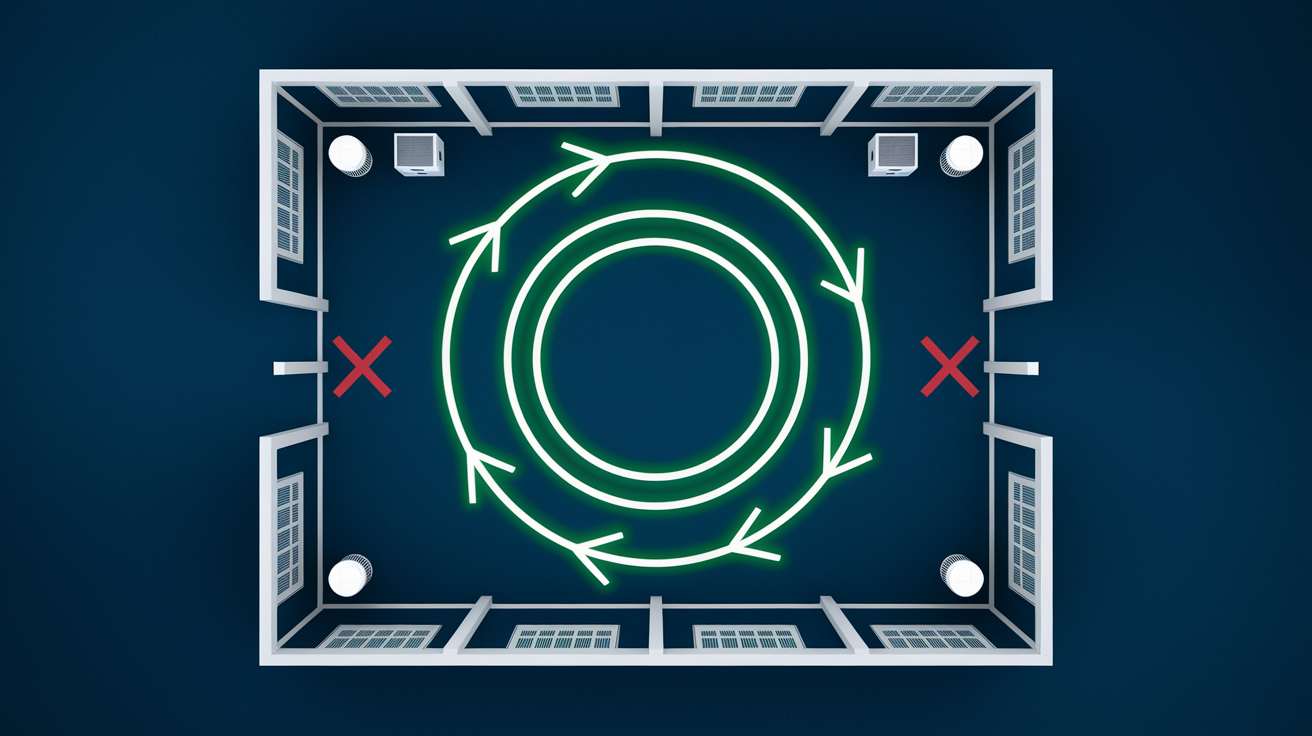
All air movers in a space should move air in the same rotational direction. Clockwise or counterclockwise doesn’t matter. Consistency does. This directional airflow prevents opposing air streams that collide and cancel velocity, creating dead zones and stagnant humid pockets around framing. Opposing airflows confuse the air circulation pattern, causing turbulence that reduces drying effectiveness. Humid air expelled from one area needs a clear path to travel toward the dehumidifier intake or exhaust point. Competing air streams disrupt that path.
Establish the pattern by starting with the wettest wall section. Position the first air mover at a 45 degree angle along that wall, creating airflow moving left to right or right to left. Your choice. Place the next unit to continue that air movement in the same direction, picking up where the first unit’s airflow tapers off. Continue around the room perimeter, maintaining the rotational direction with each additional unit. Overlap coverage areas slightly so the effective airflow zone from each unit extends into the effective zone of the adjacent unit. No gaps. No opposing directions. Just consistent circular movement that carries moisture laden air from framing surfaces toward the dehumidifier location.
Never position air movers facing each other across a space. That head on collision of air streams cancels the velocity that drives evaporation. Don’t direct air streams into each other at angles, either. Even partial opposition reduces effectiveness. If room configuration makes circular flow difficult (L shaped spaces, rooms with multiple entry points, or areas with immovable obstacles) break the space into zones and establish circular flow within each zone, linking zones through doorways or openings where air can transition from one circulation pattern to another.
Steps to Map and Establish Circular Airflow Pattern:
Walk the space and identify all framing positions affected by water, noting walls, floor joists, ceiling joists, and any enclosed cavities requiring access. Mark the wettest areas based on moisture meter readings or visual inspection, establishing priority drying zones. Plan equipment locations on paper or by taking photos and marking them up, calculating the number of air movers needed per S500 guidelines and determining where each unit will be positioned. Position the first unit at the highest priority wet area and verify air direction flows along framing surfaces at the intended 45 degree angle. Add remaining units following the circulation path established by the first unit, ensuring all air movers contribute to the same rotational direction without opposing flows.
Dehumidifier Positioning Relative to Air Movers

Position dehumidifiers centrally in the affected space with unobstructed intake and exhaust clearance. Place units at least 12 to 18 inches from walls and never in corners where airflow is restricted. Corner placement blocks the intake and exhaust openings, forcing the dehumidifier to work against itself as it tries to draw humid air in while simultaneously expelling processed air into the same restricted space. Central placement allows humid air to flow freely from all directions toward the intake while processed dry air can disperse into the space where air movers pick it up and circulate it across framing surfaces.
Establish moisture capture zones before arranging air movers, especially in larger or segmented spaces. Position dehumidifiers first, creating defined areas where moisture removal will happen. Then arrange air movers to direct humid air toward dehumidifier intakes without blowing directly into intake openings. This sequencing ensures air movers support dehumidifier function rather than working against it. For spaces exceeding 1,000 to 1,500 square feet or divided by partial walls and doorways, multiple dehumidifiers create separate zones with their own circular airflow patterns that don’t compete for the same air volume.
Never direct air mover streams straight into dehumidifier intakes. This is one of the most common and costly mistakes in structural drying. Dehumidifiers are engineered with specific airflow rates across evaporator coils that optimize moisture condensation. Blasting high velocity air from an air mover directly into the intake disrupts that designed airflow rate, changing the dwell time air spends on the cold coils. The result is significantly reduced dehumidification performance. You’re running equipment that looks like it’s working but isn’t extracting moisture efficiently. Position air movers so their airflow moves toward the general area of the dehumidifier but reaches the intake after velocity has dispersed across the room.
Maintain 30 to 50% relative humidity during active drying, monitoring with hygrometers placed at framing height in different areas of the space. Adjust equipment as conditions change and framing moisture content decreases. Early in the drying process, humidity may stay elevated (60 to 70%) until bulk moisture is removed. As drying progresses, humidity should drop. If humidity stays above 60% beyond the first 48 hours, add dehumidifier capacity or check for equipment malfunctions. LGR (low grain refrigerant) dehumidifiers provide superior moisture extraction for dense structural materials like framing, drywall, and insulation, pulling moisture more efficiently than standard refrigerant models, especially in the 40 to 60% humidity range where structural drying happens.
For more guidance on selecting the right dehumidifier for structural drying: Understanding Dehumidifier Types for Water Damage
Corner and Tight Space Air Mover Positioning Strategies
Inside corners where two walls meet trap moisture and resist drying. Poor air circulation in these convergence points allows humidity to linger even when surrounding areas are drying well. Studs at corners create framing intersections with limited airflow paths, and moisture accumulates in the trapped space where walls join. Use two air movers positioned at 45 degree angles from each adjacent wall, both directing air into the corner convergence point. This dual fan approach creates overlapping airflow that reaches the corner framing from both sides, preventing the dead zone that a single unit cannot overcome.
Tight spaces including under cabinet areas, closets, utility chases, and alcoves require low profile or compact air movers that fit in restricted spaces. Standard axial fans are too tall or wide for many of these applications. Low profile units, sometimes called “snail blowers” due to their centrifugal design and compact housing, fit under base cabinets, in closet corners, and in spaces where headroom or floor clearance is minimal. Position these units to direct air along framing runs even when clearance is limited to 6 to 10 inches. The lower airflow volume compared to full size axial fans is acceptable in tight spaces because the confined area restricts how much air can move through anyway.
Crawlspaces and basements require floor level air mover placement directing air upward at floor joists and rim joists. Position units every 8 to 12 feet of affected joist span, angling to create airflow along the joist bottom edge and across the subfloor underside. Use extension cords rated for the equipment amperage requirements. 14 gauge cords for most applications, 12 gauge for longer runs or multiple units on the same cord. Ensure adequate ventilation in confined crawlspaces to prevent carbon dioxide buildup from displacing breathable air. In summer months, monitor temperature in enclosed crawlspaces because air mover heat output can raise ambient temperature above safe working levels without ventilation.
Moisture Monitoring and Drying Progress Assessment
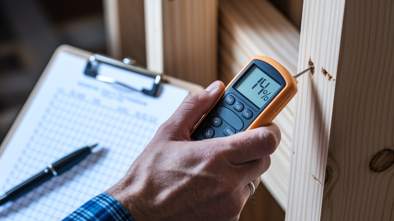
Wood framing should dry to 12 to 15% moisture content before you enclose it or install finish materials. This target range matches the equilibrium moisture content for most geographic regions, meaning the wood is in balance with the ambient environment. Enclosing framing at higher moisture content traps moisture that will continue trying to evaporate, potentially condensing on cooler surfaces inside wall cavities, creating conditions for mold growth, and causing fastener corrosion and material degradation over time. Coastal and humid climates may have slightly higher equilibrium points (14 to 16%), while arid climates may target lower moisture content (10 to 13%). Know the baseline for your region.
Take initial baseline readings documenting wet conditions before equipment placement. Measure the same locations daily at consistent times. Early morning is recommended before temperatures rise and before daily activity affects readings. Record measurements with date, time, location description, and moisture content percentage. This tracking shows drying rate progression and identifies areas not responding to air mover placement. If readings in one location decrease from 28% to 24% to 19% over three days, drying is progressing normally. If readings stay at 26% to 25% to 25%, something is wrong. Inadequate airflow, hidden moisture source, or equipment malfunction.
If moisture content readings aren’t decreasing 2 to 4% per day, adjust equipment placement. Move air movers closer to elevated readings, reducing the standoff distance from 18 inches to 12 inches or even 8 inches for stubborn areas. Add additional units to stagnant areas where only one air mover was initially positioned. Check dehumidifier functionality by verifying water extraction volume and ensuring the unit is running continuously, not cycling off due to incorrect humidity setpoint or full reservoir. Reposition equipment every 24 to 48 hours based on measurement data until all areas show consistent moisture content reduction.
As areas reach target moisture content, remove or relocate air movers from dry zones. Concentrating drying power on remaining wet areas improves efficiency and reduces power consumption. A room might start with 6 air movers positioned evenly, but by day 4, measurements show three wall sections are dry while one wall and the floor remain elevated. Remove 3 units from the dry walls and reposition them toward the wet floor area, effectively doubling air mover density where it’s still needed. This dynamic adjustment shortens total drying time compared to maintaining static equipment placement throughout the entire job.
Rotate equipment to target vertical surfaces after horizontal surfaces dry. Floor framing and lower wall sections typically dry first because moisture drains downward and low air mover placement naturally concentrates airflow in these areas. Upper wall sections and ceiling joists take longer because moisture must evaporate against gravity and airflow velocity decreases with vertical distance from floor positioned air movers. Once floor areas reach target moisture content, reangle or reposition some air movers upward toward upper walls and ceiling joists, directing drying power where it’s still needed rather than maintaining equipment on already dry surfaces.
Moisture Meter Types and Techniques for Framing:
Pin type meters for direct penetration into wood provide accurate moisture content readings at the probe depth, typically 3/8 to 3/4 inch depending on pin length. Pinless meters for non invasive surface scanning detect moisture without damaging finished surfaces, useful for checking enclosed framing through drywall before deciding on removal. Take multiple readings per framing member (top, middle, bottom, and edges) because moisture content varies within a single piece of lumber depending on exposure and grain orientation. Test both surface and core depth using longer pins or deep reading pinless meters since surface drying can occur while core moisture remains elevated. Compare readings between wet areas and reference dry areas (unaffected framing in adjacent rooms or upper floors) to establish normal baseline moisture content for your environment. Document all readings with photos showing meter display and probe position, creating visual record that supports written logs and demonstrates proper monitoring protocol was followed. Use thermal imaging cameras to identify hidden moisture pockets behind surfaces, at framing intersections, and in areas where visual and probe readings seem inconsistent with water intrusion severity.
For detailed guidance on selecting and using moisture meters correctly: How to Use a Moisture Meter After Water Damage
Water Category and Class Considerations for Placement Strategy

Water category defines contamination level and affects whether framing can be dried in place or requires removal. Category 1 water comes from clean sources like supply lines. Broken pipes, supply hose failures, or tank overflows. Category 2 water contains contaminants like washing machine discharge, dishwasher backflow, or toilet overflow with urine but no feces. Category 3 water contains pathogens, including sewage, flooding from rivers or streams, or any water that has contacted soil. Category determines restoration approach because contamination doesn’t evaporate. It stays in materials even after moisture is removed.
Category 1 and Category 2 intrusion typically allow framing to be dried in place using air movers and dehumidifiers. Structural lumber can be cleaned, disinfected if needed for Category 2, and dried to target moisture content without removal. Porous materials in contact with framing (insulation, drywall, carpet) may require removal depending on exposure duration and contamination level, but the framing itself usually survives if dried properly within 48 to 72 hours. Category 3 water often requires removal of porous materials including insulation, sometimes base plates in contact with contaminated water, and any framing with extended exposure where contamination has absorbed into wood grain. Clean, disinfect, and dry decisions become more complex and conservative with Category 3 intrusion.
Class of loss (1 through 4) describes evaporation rate potential based on material porosity and water intrusion extent. Class 1 involves minimal water absorption into materials with low porosity, typically drying in 3 to 5 days with minimal equipment. A small supply line leak affecting only a bathroom with tile floors and minimal wall contact. Class 2 involves significant absorption into some structural materials, requiring standard air mover and dehumidifier setup and typically 5 to 7 days drying time. Water affecting carpet, pad, and base of drywall in multiple rooms. Class 3 involves water intrusion from overhead, saturation of walls and ceilings, and significant absorption into low evaporation materials, requiring maximum equipment density and 7 to 14 days drying. Ceiling leak soaking insulation and drywall throughout rooms below. Class 4 involves specialty materials with very low porosity and permeability like hardwood floors, plaster, concrete, or stone, requiring specialized low velocity high density air movers, mat systems, or injection drying techniques and potentially 14 to 21+ days of drying.
Higher class losses and Category 2 or 3 water require more aggressive air mover placement with higher CFM output and closer spacing to achieve adequate drying before microbial growth begins. Category 1 Class 1 loss might need only 3 to 4 air movers in a moderate room. Category 3 Class 3 loss in the same room could require 8 to 10 air movers plus specialty drying equipment and antimicrobial treatments. Equipment density directly correlates with loss severity because time becomes the critical factor. Microbial growth begins within 24 to 48 hours under favorable conditions, and more severe water intrusion creates more favorable conditions across more surface area.
Safety Considerations for Air Mover Operation

Calculate total amperage load before plugging in equipment. Each professional air mover draws 2.5 to 5 amps depending on motor size and speed setting. A standard 15 amp household circuit can safely handle 12 amps of continuous load (80% of rated capacity per electrical code). That’s 2 to 3 professional air movers per circuit maximum. Exceeding this limit trips breakers, creates fire hazards from overheated wiring, and potentially damages equipment. Map electrical circuits in the affected space before placement, identifying which outlets share circuits and distributing air movers accordingly across multiple circuits to balance load. Large drying jobs may require generator power if existing circuits can’t support equipment load.
Heavy duty extension cords rated for equipment amperage are required for most drying setups. Use 14 gauge cords for single air movers or short runs under 25 feet. Use 12 gauge cords for multiple units on the same cord or runs exceeding 50 feet. All cords must have grounded three prong plugs matching the equipment plugs. Never use two prong adapters or remove ground pins to force three prong plugs into two prong outlets. Moisture environments demand proper grounding for safety. Inspect cords for damage, fraying, or exposed wire before use. Wet environments plus damaged cords equal electrocution risk.
Secure cords with tape or cord covers across walkways to prevent trip and fall hazards. Position air movers against walls when possible rather than in the middle of traffic paths. Mark equipment locations with caution tape or warning signs in low light areas where units are harder to see. Basements and crawlspaces with minimal lighting become obstacle courses when filled with air movers, dehumidifiers, and crisscrossing extension cords. Step carefully. Scan with a flashlight. Move deliberately.
Safety Checklist Before Starting Equipment:
Verify all circuits are functional and electrical components are completely dry with no standing water near outlets or panels. Test GFCI outlets for proper function using the test/reset buttons, ensuring ground fault protection is active in wet environments. Inspect equipment power cords for damage, proper strain relief at plug connections, and absence of repairs with electrical tape that compromise water resistance. Clear walking paths of debris, tools, and materials that create trip hazards when combined with cords and equipment placement in confined or dark spaces. Establish equipment shutdown protocol for nighttime or unattended operation, including who will monitor equipment, how to reach them in emergency, and conditions that require immediate shutdown.
Common Air Mover Placement Mistakes to Avoid
Even well intentioned equipment placement can be ineffective or counterproductive if common mistakes aren’t recognized and avoided. Extending drying time from 5 days to 10 days doubles electrical costs and increases risk of secondary damage including mold growth and structural degradation. Poor placement also creates liability concerns when moisture problems emerge weeks or months later because framing wasn’t adequately dried. Recognizing these frequent errors helps avoid wasted time, money, and materials.
Common Mistakes:
Placing too few air movers based on visual assessment rather than IICRC S500 calculations. If the affected area looks “not that wet,” the temptation is using 2 to 3 units when calculations require 6 to 8, extending drying time significantly. Positioning air movers facing each other creating opposing airflows that cancel velocity at the collision point, creating a dead zone exactly where airflow is most needed. Blowing directly into dehumidifier intakes reducing efficiency by 30 to 50% as excessive velocity disrupts the designed airflow rate across evaporator coils. Placing units too far from wet surfaces beyond 18 to 24 inches, where airflow velocity drops below levels needed for effective evaporation and surface coverage becomes spotty. Failing to address corners and dead zones where natural air circulation is poor, leaving isolated pockets of high moisture content that require dedicated equipment positioning. Running air movers without dehumidifiers, which only moves moisture saturated air around the space without extracting moisture, achieving no net drying progress. Stopping equipment too early before moisture meters confirm target levels are reached, relying on visual dryness or schedule pressure instead of measured data.
Proper placement requires both initial planning using industry formulas and ongoing adjustment based on moisture monitoring. Most mistakes stem from either inadequate equipment quantity or poor understanding of how air movement and moisture removal work together as a system. Fans evaporate moisture from materials. Dehumidifiers capture that moisture from the air. Neither works effectively alone. Positioning must account for both functions, creating airflow patterns that move moisture from materials toward dehumidifier intakes without interference or gaps in coverage. Skip the shortcuts. Follow the math. Monitor the measurements. Adjust when data says adjustment is needed.
Documentation and Progress Tracking Methods
Documentation serves three purposes: supporting insurance claims, demonstrating contractor accountability, and creating reference records if disputes or mold issues arise later. Without photos and logs proving proper restoration protocol was followed, you’re defending decisions from memory weeks or months after equipment was removed. Moisture problems discovered during renovation or sale negotiations become your liability when you can’t demonstrate the work was done correctly. Photos and written records close that gap.
The three core documentation elements are initial setup photos, floor plan sketch, and daily moisture meter readings. Setup photos show equipment placement and affected areas before drying begins. Capture wide angle room views showing all air mover positions, close ups of individual units with angle and distance visible, dehumidifier placement relative to air movers, and affected framing areas with visible damage or removed materials. Floor plan sketch doesn’t require drafting skills. A hand drawn outline of the room with dimensions, marked air mover locations numbered or labeled, arrows showing airflow direction, and dehumidifier position provides clear reference. Moisture meter readings logged with date, time, specific location description (not just “wall” but “north wall, 3rd stud from left corner, 18 inches above floor”), and measurement value create the data trail proving drying progress.
Digital tools simplify tracking without adding complexity. Smartphone photos automatically embed timestamp and location data in image files, providing verification of when and where photos were taken. Some moisture meters include Bluetooth connectivity and companion apps that store readings with GPS coordinates, automatically building a database of measurements organized by date and location. Simple spreadsheet templates on a phone or tablet allow real time data entry on site without paper forms that get wet, lost, or illegible. The tools don’t need to be expensive. Basic smartphone features and free apps handle most documentation needs effectively.
| Day | Location | Moisture % | Equipment Changes | Notes |
|---|---|---|---|---|
| 1 | North wall, stud 3 | 28% | Placed 6 air movers, 1 dehumidifier | Baseboards removed, drywall intact |
| 2 | North wall, stud 3 | 24% | None | Drying progressing normally |
| 3 | North wall, stud 3 | 19% | Removed 2 air movers from dry east wall | East wall reached 14%, concentrated equipment on north wall and floor |
| 4 | North wall, stud 3 | 16% | None | Continuing until target 13 to 14% reached |
| 5 | North wall, stud 3 | 13% | Removed all equipment | Target reached, approved for reconstruction |
Residential vs Commercial Framing Drying Setups
Residential water damage jobs typically involve 1 to 3 rooms with 3 to 8 air movers total and a single dehumidifier serving the affected space. A bathroom supply line failure might need 3 air movers and 1 dehumidifier running for 4 to 5 days. A basement with seepage along one foundation wall might need 5 to 6 air movers and 1 to 2 dehumidifiers for 5 to 7 days. Equipment fits through doorways, plugs into existing household circuits with load balancing, and can be monitored by the homeowner or a technician checking daily. Containment is usually minimal. Close doors to unaffected areas and maintain climate control.
Commercial projects span entire floors requiring 15 to 30+ units with zone based drying strategies and multiple dehumidifiers creating separate moisture capture areas. An office building pipe burst affecting 3,000 square
Final Words
Getting air mover placement for drying framing right comes down to following the IICRC formulas, positioning units at proper angles, and keeping everything running until your moisture meter confirms target levels.
The 45-degree angle rule, the circular airflow pattern, and the dehumidifier coordination aren’t optional steps. They’re what separate a clean dryout from a mold problem three months later.
Start with the calculations, place your equipment, check your readings daily, and adjust as you go. Framing that’s actually dry doesn’t just look better. It performs better and lasts longer.
FAQ
Q: Where should you place an air mover to dry water damage?
A: Air movers should be placed at a 45-degree angle toward wet framing surfaces, positioned 12-18 inches away from studs, joists, or subfloor. Direct airflow along the entire length of wet walls and framing members, spacing units every 10-16 feet for consistent coverage.
Q: How long can you leave an air mover running during structural drying?
A: Air movers can run continuously for 24 hours per day during active structural drying, which typically takes 3-7 days depending on conditions. IICRC S500 standards require continuous operation until moisture meter readings confirm framing has reached 12-15% moisture content targets.
Q: How many air movers per square foot are needed for drying framing?
A: You need 1 air mover per 50-70 square feet for wet floors and lower walls up to 2 feet high. Add 1 air mover per 100-150 square feet for upper walls and ceilings, plus 1 additional unit for each wall inset or offset exceeding 18 inches.
Q: How do you use an air mover to dry carpet and underlying subfloor?
A: Position air movers at floor level directing airflow underneath carpet edges and across padding to reach the subfloor beneath. Angle units at 45 degrees and space every 10-16 feet to move air across wet layers, running continuously with a dehumidifier operating simultaneously.
Q: Why must dehumidifiers run alongside air movers during structural drying?
A: Dehumidifiers must run with air movers because fans only evaporate moisture from surfaces while dehumidifiers extract that moisture from the air. Without dehumidifiers, humid air circulates and moisture reabsorbs into framing, preventing effective drying and enabling mold growth.
Q: What is the proper angle for air mover placement when drying framing?
A: The proper angle for air mover placement is 45 degrees toward wet framing surfaces. This angle maximizes evaporation rate across wood grain and surface area while preventing over-drying from direct perpendicular airflow concentrated on one spot.
Q: How do you create effective airflow patterns around framing with multiple air movers?
A: Create circular airflow by positioning all air movers to move air in the same rotational direction, either clockwise or counterclockwise around the room. Start at the wettest wall section and add units following the circulation path, overlapping coverage areas slightly.
Q: When should you reposition air movers during the drying process?
A: Reposition air movers every 24-48 hours based on moisture meter readings. If readings aren’t decreasing 2-4% per day, move units closer to elevated moisture areas, change angles to target problem zones, or add equipment to stagnant spots.
Q: How do you position air movers for drying wall cavities and hidden framing?
A: Position air movers at floor level angling upward into wall cavities through baseboard removal areas or drilled access points. This creates airflow along stud faces inside enclosed bays where hidden moisture trapped behind walls presents the greatest long-term risk.
Q: What spacing distance should air movers maintain from wet framing surfaces?
A: Air movers should maintain 12-18 inches distance from wet framing surfaces. This spacing prevents over-drying damage to wood while ensuring adequate air velocity reaches the surface for effective moisture removal across the entire affected area.
Q: How many air movers are needed for a typical residential water damage job?
A: A typical residential water damage job requires 3-8 air movers depending on affected area size. Start with 1 air mover per room minimum, then calculate additional units based on 1 per 50-70 square feet of wet floor or 1 per 100-150 square feet of wet ceiling.
Q: Should air movers blow directly into dehumidifier intake openings?
A: Never direct air movers straight into dehumidifier intakes because this disrupts the designed airflow rate across evaporator coils and significantly reduces dehumidification performance. Position air movers to direct humid air toward dehumidifiers without blowing directly into intake openings.
Q: How do you dry floor joists and subfloor using air movers?
A: Position air movers in the basement or crawlspace pointing upward at the subfloor underside, angling along joist direction to move air across the entire joist span. When flooring is removed, place units on the subfloor directing air across plywood or OSB panels.
Q: What CFM rating do air movers need for structural drying applications?
A: Most structural drying applications require air movers rated at 1,200-3,000 CFM per unit. Professional axial fans deliver high airflow for open framing, while centrifugal blowers provide higher pressure for wall cavities and enclosed spaces requiring focused air penetration.
Q: How do you position air movers in corners where moisture accumulates?
A: Position two air movers at 45-degree angles from each adjacent wall, directing air streams into the corner convergence point. Inside corners trap moisture due to poor air circulation and require dual units to create adequate airflow in these problematic areas.
Q: What moisture content target indicates framing is dry enough to close up?
A: Dimensional lumber framing should dry to 12-15% moisture content before enclosing or installing finish materials. This matches ambient equilibrium moisture content for most geographic regions and prevents trapped moisture from causing mold growth or wood decay behind closed walls.
Q: How does water category affect air mover placement strategy for framing?
A: Category 1 and 2 water typically allows framing to be dried in place using air movers and dehumidifiers positioned for maximum airflow. Category 3 water often requires removal of porous materials and more aggressive air mover placement to achieve drying before microbial growth begins.
Q: What is the biggest mistake when placing air movers for structural drying?
A: The biggest mistake is aiming air movers only at visible wet spots while ignoring hidden moisture in wall cavities, behind baseboards, and under flooring. Hidden moisture presents greater long-term risks including structural decay and mold growth that develops unseen.
Q: How do you position air movers for drying exposed ceiling joists?
A: Angle air movers upward from floor level or position on scaffolding directing air along joist bottom edges and into joist bays. Add 1 air mover for each 100-150 square feet of wet ceiling area, focusing airflow along the entire joist span.
Q: Should air movers be placed on dry areas during structural drying?
A: Air movers should only be placed on wet surfaces, not dry areas. Concentrate equipment on moisture-affected zones confirmed by meter readings to maximize drying efficiency, reduce power consumption, and avoid wasting equipment capacity on areas that don’t need treatment.
Q: How do you document air mover placement for insurance claims?
A: Document air mover placement with three elements: initial setup photos showing equipment and affected areas, floor plan sketch marking air mover locations and airflow directions, and daily moisture meter readings logged with date, time, location, and measurement values.
Q: What electrical capacity do air movers require during operation?
A: Most professional air movers draw 2.5-5 amps per unit. A standard 15-amp circuit safely handles 2-3 professional air movers. Distribute units across multiple circuits to avoid overloading, and use heavy-duty extension cords rated for equipment amperage with grounded plugs.
